Harness overview
There are two versions of the cable harness: B2 and C1. Please refer to the cable harness marking to know which version i.e B2 or C1 (see the below picture).
Example of cable marking:
1047-141-06 B2
1047-141-06 C1
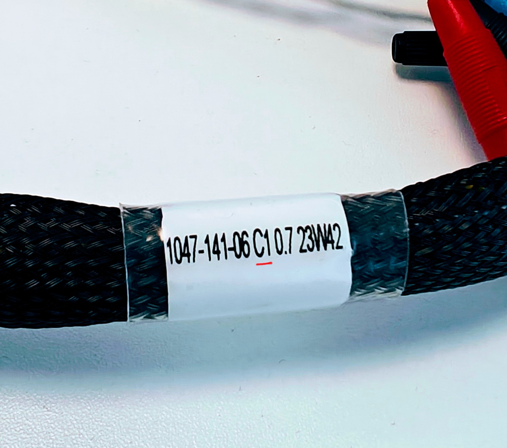
Example of C1 Cable harness marking
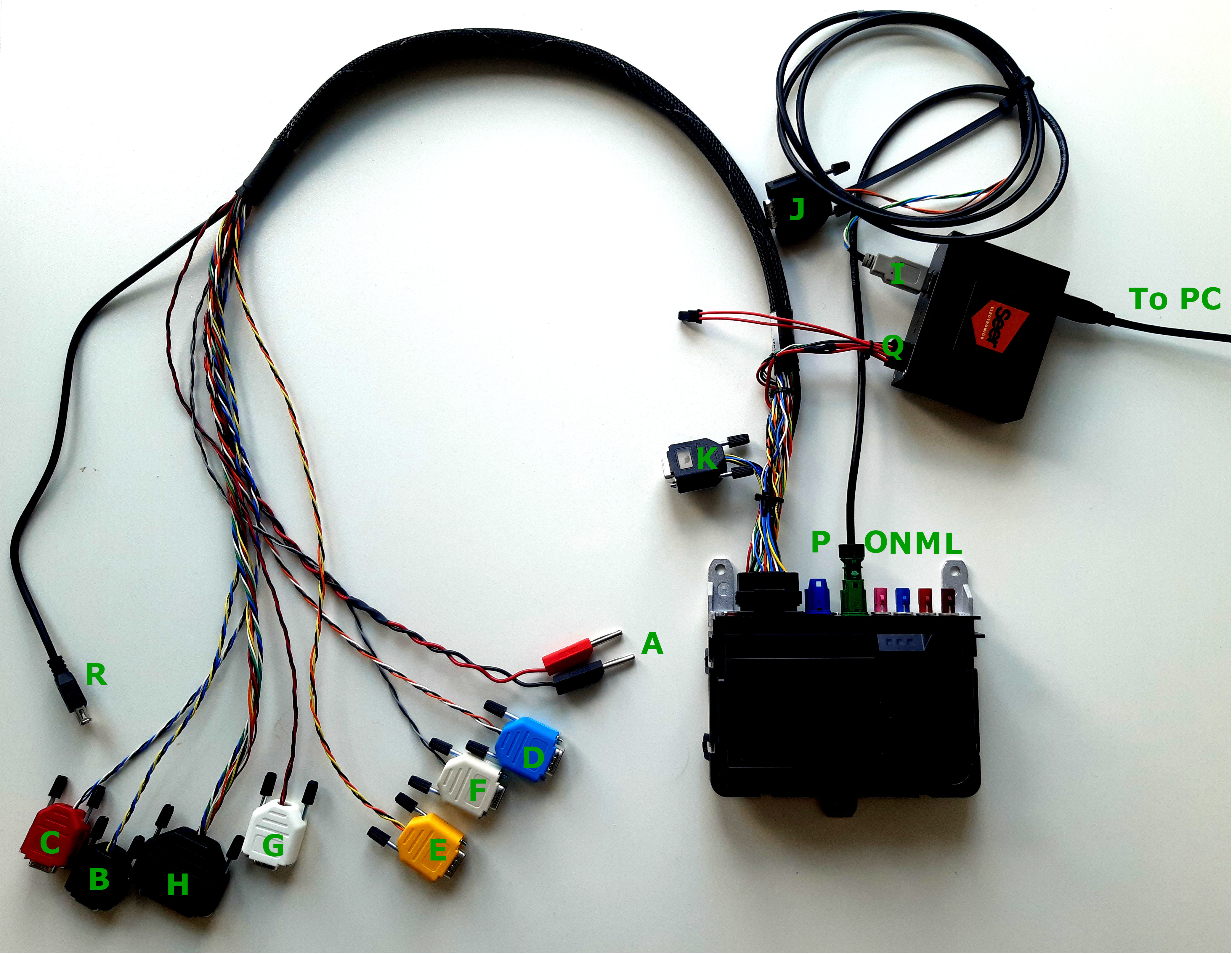
Setup using cable harness version B2
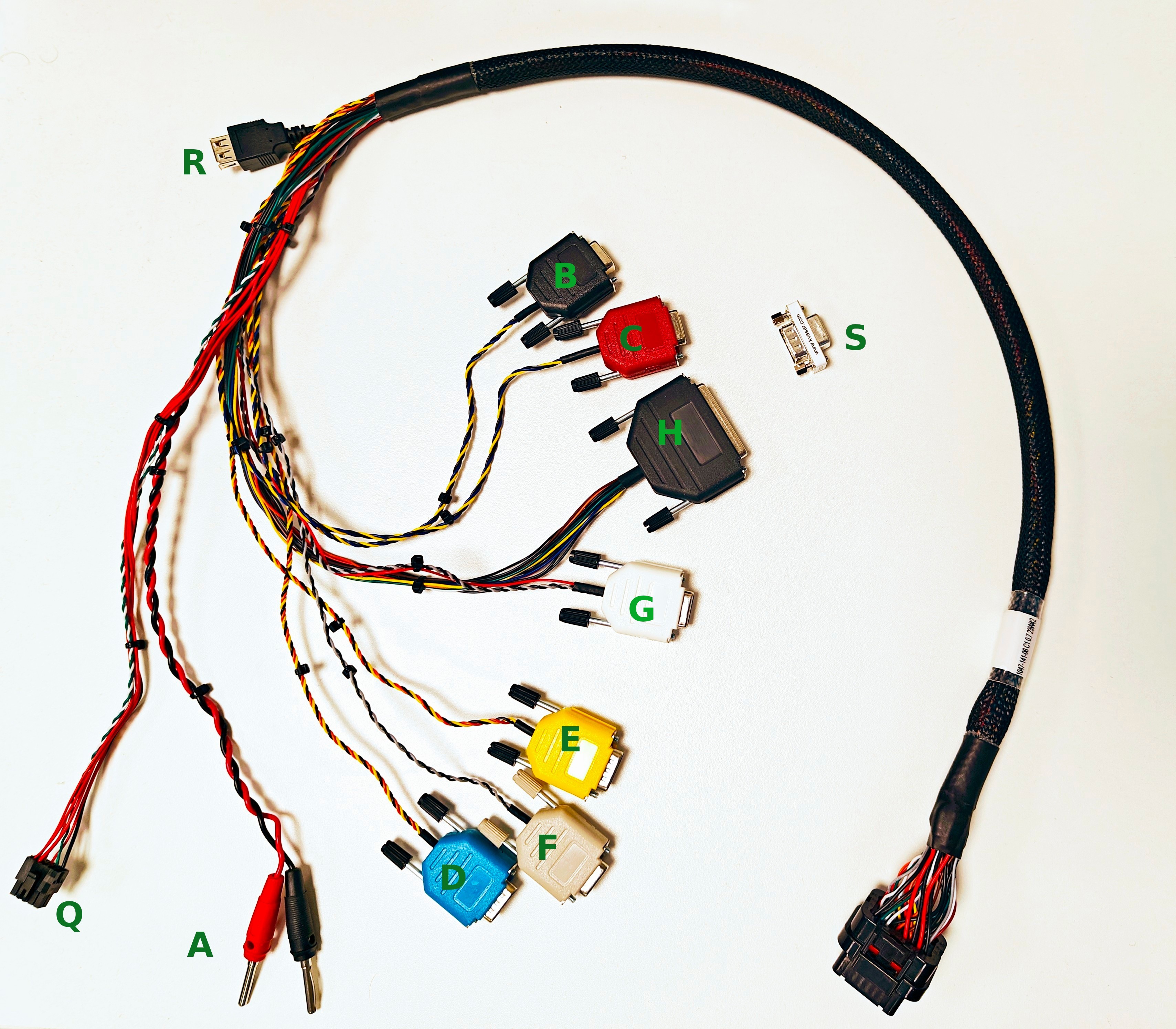
Cable harness version C1
Function |
||
|---|---|---|
Designator |
Version B2 |
Version C1 |
A |
Power Supply (12 V) |
Power Supply (12 V) |
B |
CAN1 (can0) |
CAN1 (can0) |
C |
CAN2 (can1) |
CAN2 (can1) |
D |
RS-485 |
RS-485 |
E |
RS-232 |
RS-232 |
F |
Reserved for future use |
Reserved for future use |
G |
Reserved for future use |
Reserved for future use |
H |
I/O |
I/O |
I |
Debug USB |
Debug USB |
J |
T1 |
T1 |
K |
CAN termination |
Not available |
L |
External LTE Antenna |
External LTE Antenna |
M |
External LTE Antenna |
External LTE Antenna |
N |
External GNSS Antenna |
External GNSS Antenna |
O |
External Wi-Fi Antenna |
External Wi-Fi Antenna |
P |
Ethernet |
Ethernet |
Q |
CDP switch power connector |
CDP switch power connector |
R |
Host USB |
Host USB |
S |
Not available |
CAN Termination adapter |
H connector (I/O) pinout |
|
|---|---|
Pin |
Function |
Pin 2 |
AIN1 |
Pin 3 |
Ground |
Pin 4 |
AIN3 |
Pin 5 |
Ground |
Pin 6 |
DIN1 |
Pin 7 |
Ground |
Pin 11 |
DOUT2 |
Pin 15 |
AIN2 |
Pin 16 |
Ground |
Pin 17 |
AIN4 |
Pin 18 |
Ground |
Pin 20 |
Ground |
Pin 23 |
DOUT1 |
Hardware setup
Connect
IandQto the CDP switch andAto a power supply. Ensure the CDP switch is functioning properly, for example as indicated by green LED status lights.Turn on the power to the ACU6-Pro device. A new network interface should be present on the PC. To make sure the device stays on, enable ONSW (Power Management):
$ ./utils/onsw.sh on
VirtualBox users are advised to add the USB device
Linux
x.y.z-acu6 ... RNDIS/Ethernet ...
to the USB Device Filters list. To get to the add device view, right click on your virtual machine and then click Settings -> USB.$ ip address ... 108: enx001122334455: <BROADCAST,MULTICAST> mtu 1500 qdisc fq_codel state DOWN group default qlen 1000 link/ether 00:11:22:33:44:55 brd ff:ff:ff:ff:ff:ff ... $
Configure the network interface with the static IP address 198.18.1.2 and netmask 255.255.255.0.
Temporarily this can be done with the following commands, the netmask is here converted into a prefix (255.255.255.0 -> /24):
$ sudo ip address add 198.18.1.2/24 dev enx001122334455
$ sudo ip link set enx001122334455 up
The above will last until the ACU6 is rebooted.
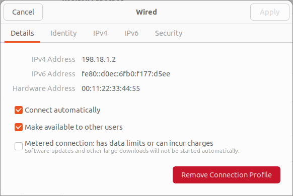
To make the change persistent, configure the address and netmask in Network Manager.
Identify which Wired connection it is by opening the details using the Cog and checking Hardware Address for the expected MAC (00:11:22:33:44:55).
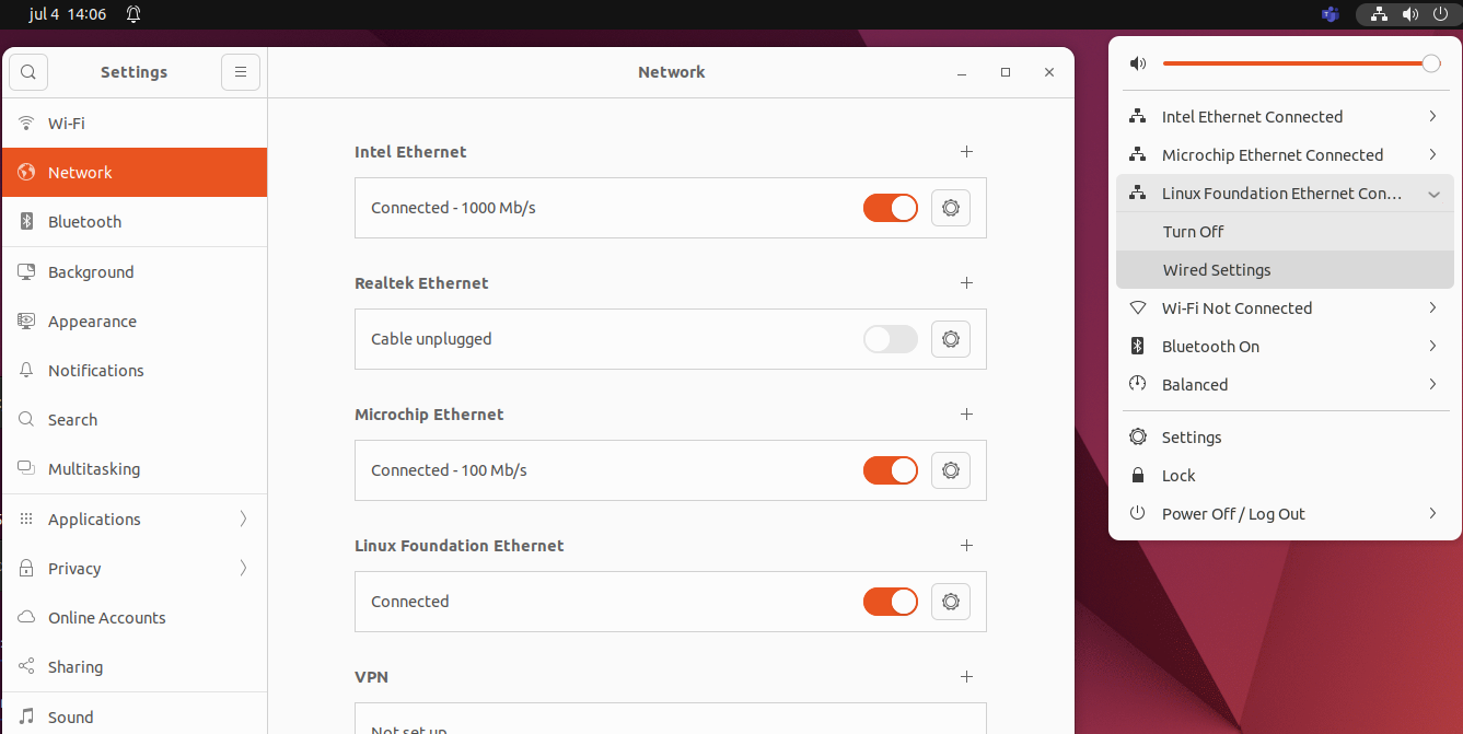
Configure the checkboxes like this in the Details tab:
Configure the ip address and netmask like this in the IPv4 tab:
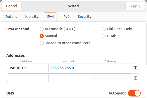
Save settings with Apply, switch the interface off if it’s on, then switch it on.
Now the network interface
enx001122334455should have the static IP address 198.18.1.2 and netmask 255.255.255.0.$ ip address ... 108: enx001122334455: <BROADCAST,MULTICAST,UP,LOWER_UP> mtu 1500 qdisc fq_codel state UP group default qlen 1000 link/ether 00:11:22:33:44:55 brd ff:ff:ff:ff:ff:ff inet 198.18.1.2/24 brd 198.18.1.255 scope global enx001122334455 valid_lft forever preferred_lft forever inet6 fe80::211:22ff:fe33:4455/64 scope link valid_lft forever preferred_lft forever ... $